Controls
- Level– Controls the output volume
- Tone – Adjusts the tonal response
- Gain – Controls the amount of signal gain
Specifications
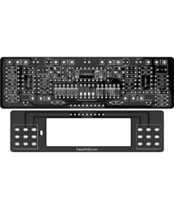
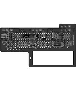
- Designed for a 125B enclosure with top-mounted jacks


The company, product and service names used in this web site are for identification purposes only. All trademarks and registered trademarks are the property of their respective owners. This product is not manufactured or distributed by Boss, maker of the Boss BD-2 Blues Driver.
PedalPCB is not affiliated with Boss or Roland Corporation.
| Weight | .275 oz |
|---|---|
| Dimensions | 1.95 × 1.95 × 0.5 in |
7 reviews for Cobalt Drive
Only logged in customers who have purchased this product may leave a review.
Related products
Out of stock
couch.rich (verified owner) –
Sounds exactly like my Blues Driver with a TL071. If you upgrade the chip you’ll be pleased at some of the “transparency” you can achieve while still calling on a really nice gain range!
Stephan Gilberg (verified owner) –
Sounds great, nice pcb layout, works very well! Great recreation of a classic.
christopher_s_morgan (verified owner) –
Just as crystal clear as you would expect a Boss pedal to be. I actually like it better so far with some hotter humbuckers and the gain dailed way back for the super bright blues tone, and all the way up for a searing lead tone. Very happy with this build and super easy to assemble. Great for beginners.
Crispyfunk (verified owner) –
this circuit has the perfect clean’ish blues crunch tone all the way to 80s metal sounds , or even a nice clean booster with tone shaping options . the layout is clean . everyone should have a Blues Driver (Cobalt Drive)
Crispyfunk (verified owner) –
Sounds exactly like the Boss Blues Driver , very nice pcb.
Steve Walker (verified owner) –
Oh, my goodness! This is one of my Top 10 pedals (and I own a LOT of pedals). The range of tones is outstanding, and the low-end punch chugs with just the right amount of breakup. Yes, I can actually chug with this thing! Not that it’s a heavy distortion or anything. (I’ll stack it with a distortion pedal, if need be.) A fun build and an extremely usable drive pedal.
A+
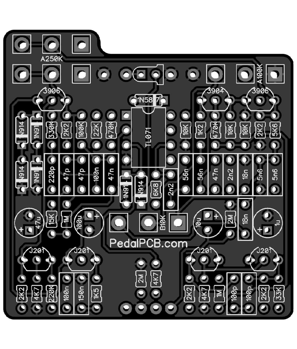
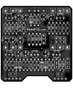
Morgon Kanter (verified owner) –
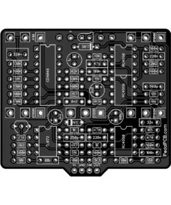
This board needs a layout revamp for the current times. J201 JFETs only come in SMD format anymore, and we solder them onto adapter boards. Two of these (left hand side of the picture) are badly placed for this new reality, with on one side the 100n and 150n capacitors crowding them out, and the other side the 47u and 100u electrolytic capacitors. They could also use slightly more space between them, as the adapter boards run into each other. Had to get pretty creative installing those two pieces because of this. It was ultimately doable but I’m concerned about their long-term survival against bumps and jolts because of how I had to place them. Ultimately I think the board needs to be laid out again with the new JFETs in mind.